Lab 2
Preview and Code Restructuring
In this lab, we integrated the ICM-20948 IMU sensor into our Artemis board. Following the setup instructions for the IMU was very straightforward, and no major issues were run into during the programming of the board with a test script. However, during this time, I added a major code restructuring into the Arduino script. Previously, the primary .ino file was the provided arduino_ble.ino, but this wasn't ideal to me since structuring around BLE made it difficult to add or change board functionality. Inspired by my previous experience building and maintaining C++ projects, I changed arduino_ble into a header file, and defined a completely different main.ino file. setup() and loop() in arduino_ble simply became ble_setup() and ble_loop(), and these were essentially the only thing called inside the main.ino file before integrating the IMU further. This was done from the beginning since I anticipated much more difficulty if I had attemped this restructuring when it was required later on in the lab. To complete the earlier sections of the lab, I simply added another imu_setup() (defined in a new header file dedicated to the IMU) and imu_loop(), and selectively commented out the loop I didn't want to execute.
Adding the IMU
Installing the IMU library in the Arduino IDE went smoothly. I initially just uploaded the script directly to the Artemis, but was confused when the Artemis wasn't able to properly connect to the IMU. Turns out, I had overlooked AD0_VAL. Reading the comments in the provided example code, I inspected the IMU and found that since the ADR jumper was closed, AD0_VAL should be set to 0. Adding this change to my code resulted in a functioning IMU and data printed to console.
After experimenting a bit with the IMU, I found all the sensor data to be relatively accurate. Acceleration changed when I moved the IMU around, and by testing, I figured out how the axes of the IMU aligned with the physical board. Likewise, gyro data was non-neglible when I was actively rotating the IMU about some axis. However, the magnetometer was a little trickier to get meaningful data out of it. However, I eventually figured out that bringing the IMU closer to electronically noisy things like my laptop or phone could induce large changes in the data.
| Test Script | AD0_VAL |
|---|---|
 |
Getting Pitch and Roll
Next, I refreshed myself with the pitch and roll equations from class. Taking advantage of the fact that gravity will always point down, I rederived the equations given on the slides in class. Using atan2() as suggested, I implemented roll as being atan2 with X-direction acceleration over Z-direction acceleration, and pitch as being atan2 with Y-direction acceleration over Z-direction acceleration. Note that not included in the screenshot is a helper function I added to convert between degrees and radians, to make my code more readable.
| Pitch and Roll Functions |
|---|
 |
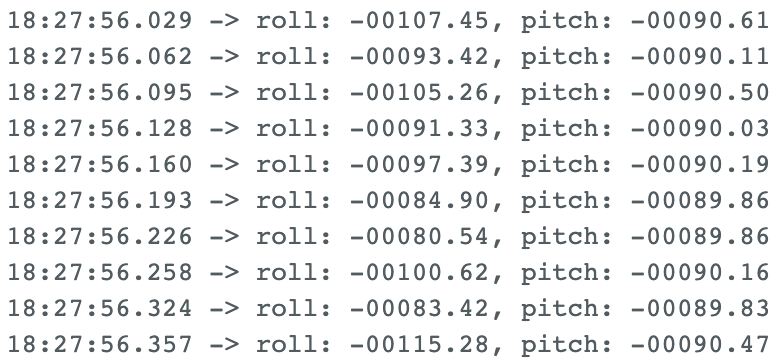
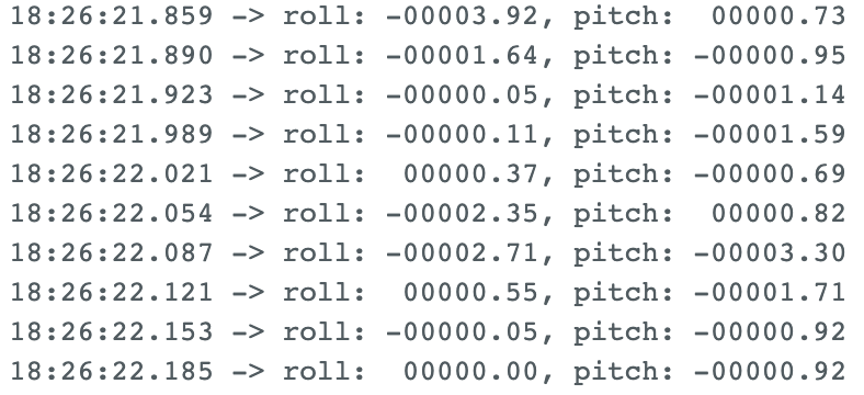
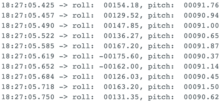
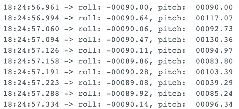
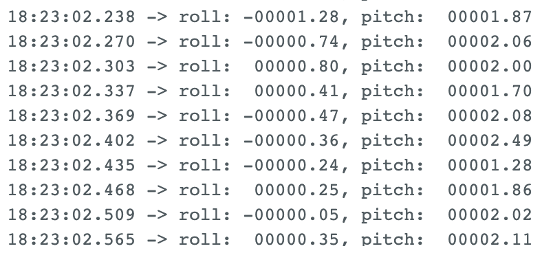
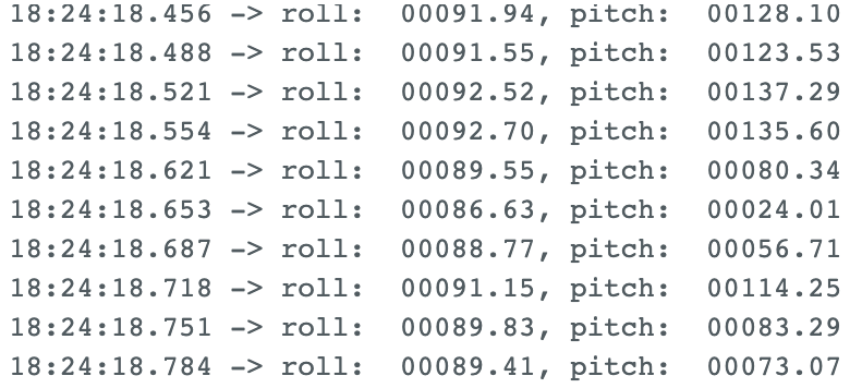
Next, I tested the limits of the system. For both pitch and roll, I've included screenshots of the serial monitor output when holding the IMU at -90, 0, and 90 degrees. Overall, I found the sensor to be very accurate. I had expected much more variance in data around 90 degrees since the axes would be perpendicular to the floor, and thus any noise in the raw acceleration data could cause large swings in pitch and roll output data. However, I found my sensor to be remarkably resilient to this. I, for one, am definitely not complaining about not needing a two-point calibration.
| Pitch @ -90 | Pitch @ 0 | Pitch @ 90 |
|---|---|---|
 |
 |
 |
| Roll @ -90 | Roll @ 0 | Roll @ 90 |
 |
 |
 |
Fourier Transforms
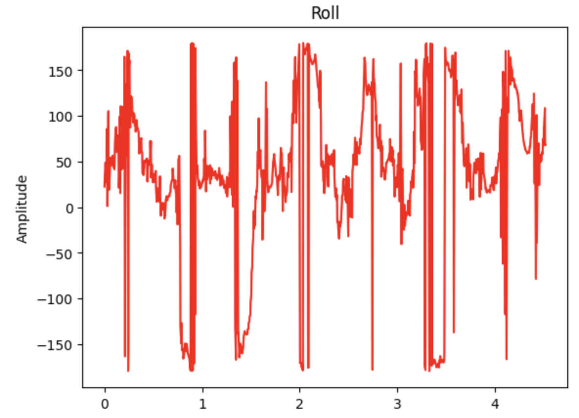
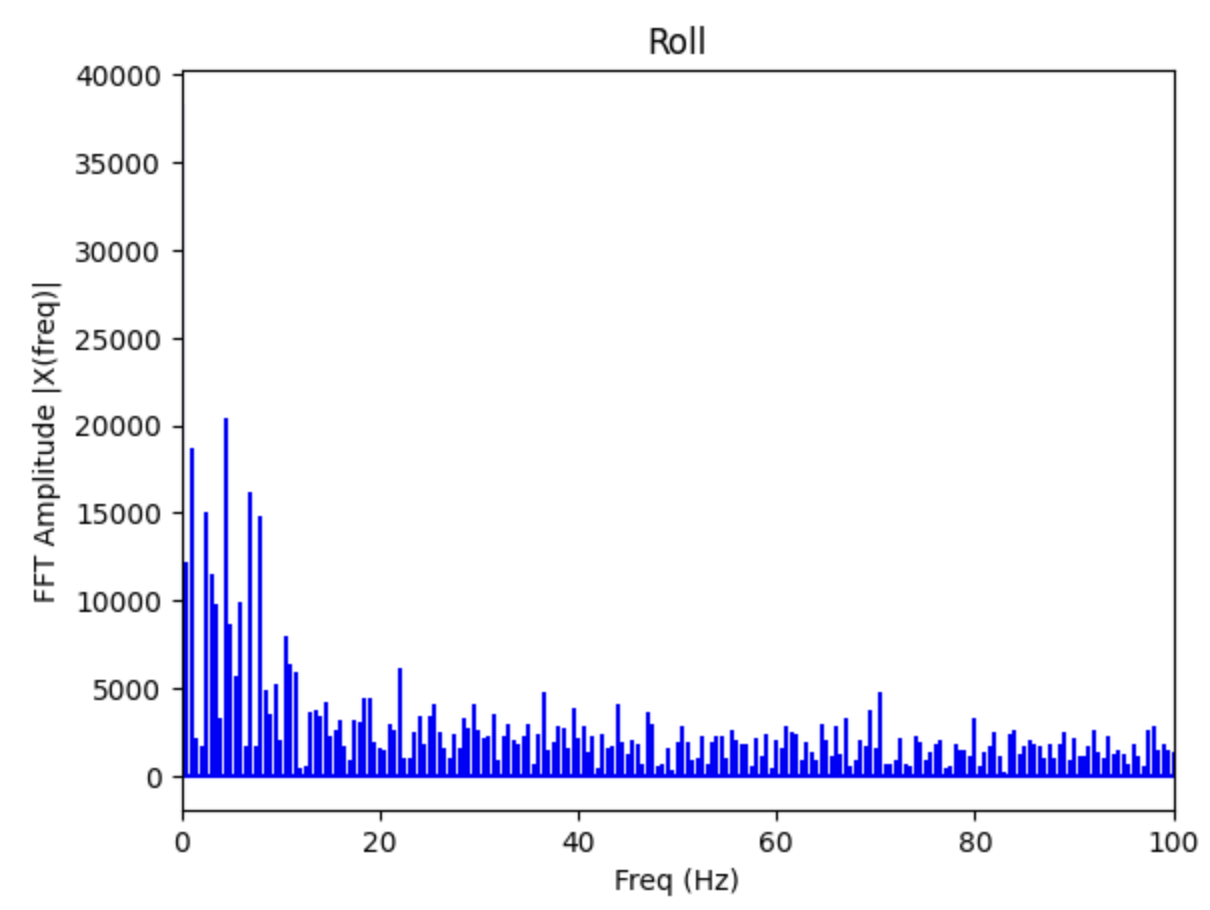
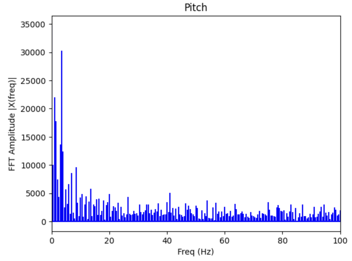
Since the data still had some noise, I decided to run a fourier transform to analyze it. First, I added a command very similar to the temperature data gathering command from the previous lab. When the Artemis receives this command, it simply records all of its IMU data for 500 datapoints before sending it all back to my laptop, where I can properly analyze it. In my jupyter notebook, I store the data, and use it and the timestamps to integrate the gyro data to get heading. While I don't use this data for now, I figured I would have to eventually implement it later anyways. Using this site as a guide, I implemented a basic Fast Fourier Transform and got the data below, which is the output generated from me moving the IMU around randomly.
| Roll w/o FFT | Roll with FFT |
|---|---|
 |
 |
| Pitch w/o FFT | Pitch with FFT |
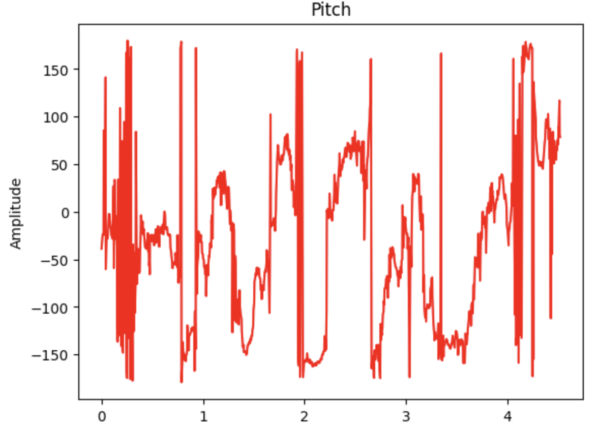 |
 |
Low Pass Filter
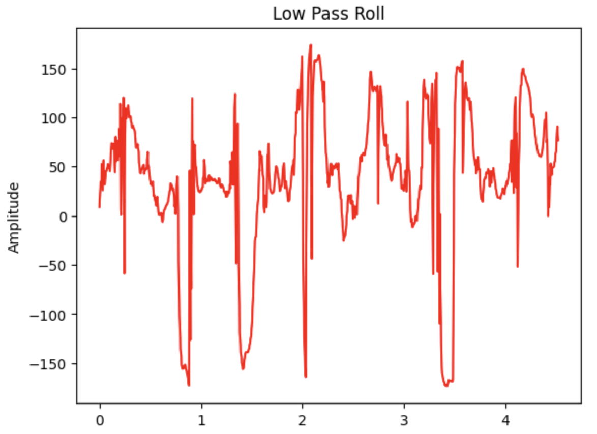
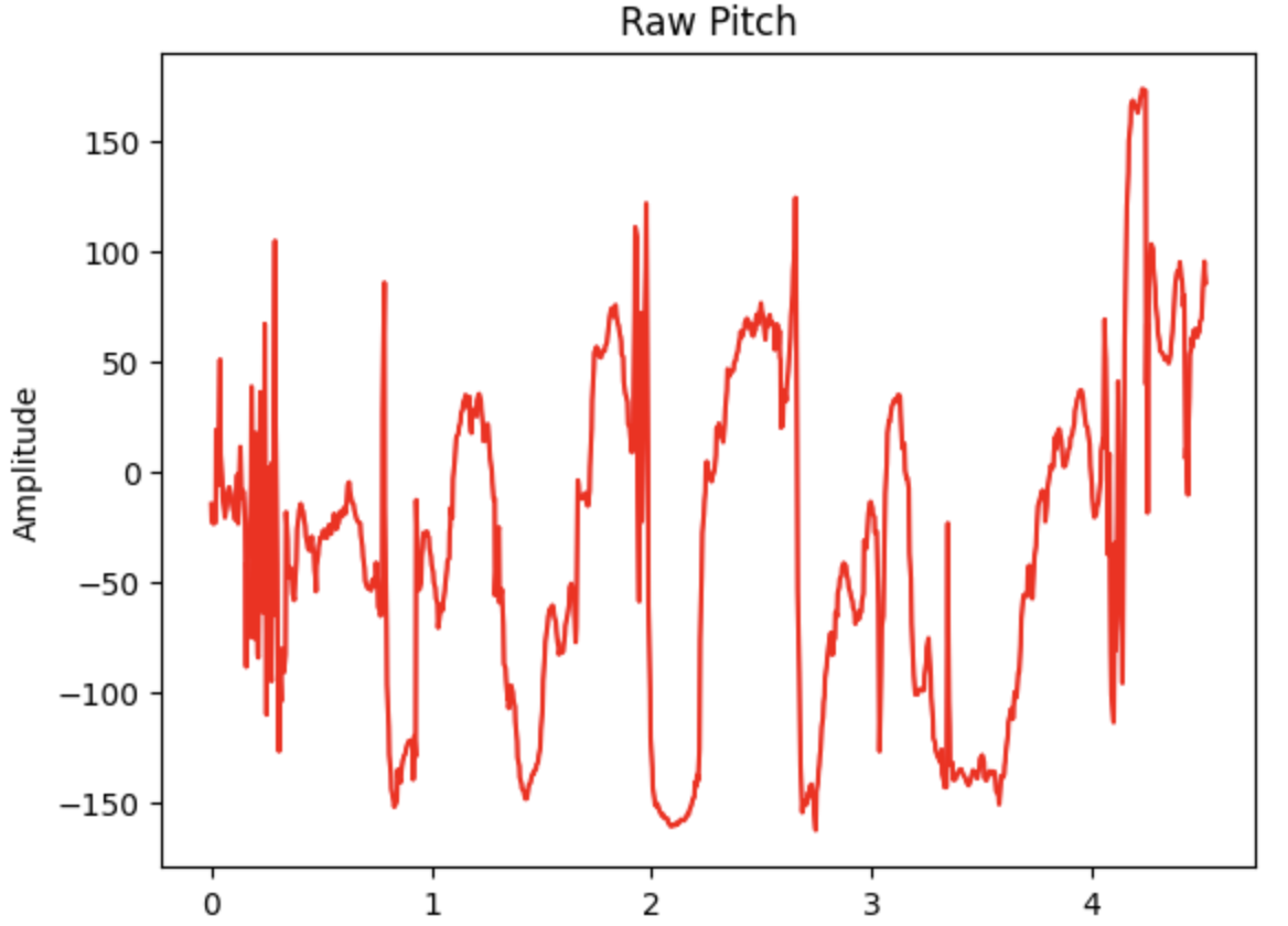
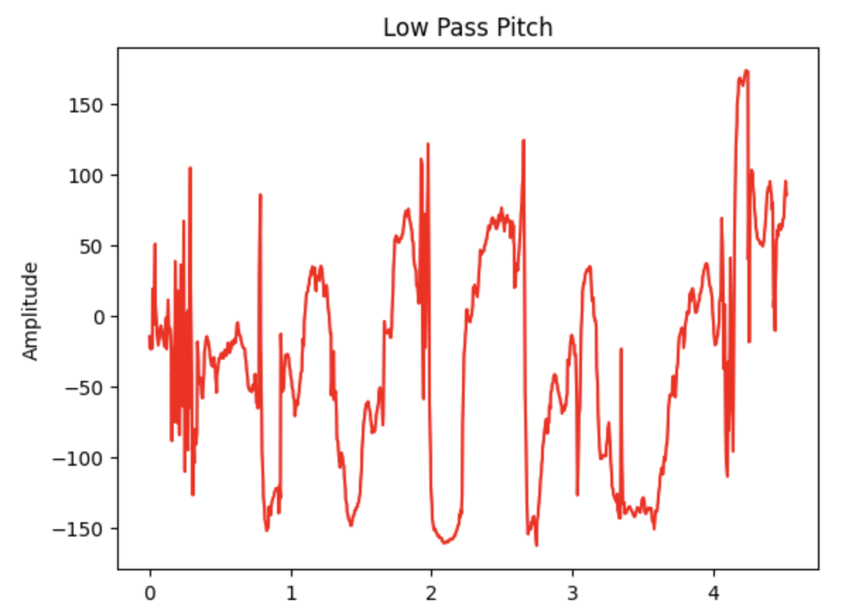
Based on the fourier transform data, I decided to implement a cutoff frequency at 10 Hz for both axes, since this seemed to be the point past meaningul signals of non-negligible magnitudes for both pitch and roll. This decision was further supported by the maximum sample rate of the accelerometer (plus time for storing the data), which seemed to be around 220 Hz on average, meaning it could capture all the relevant signals we wanted to see.
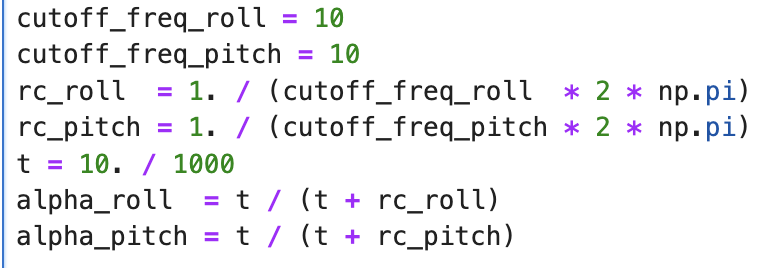
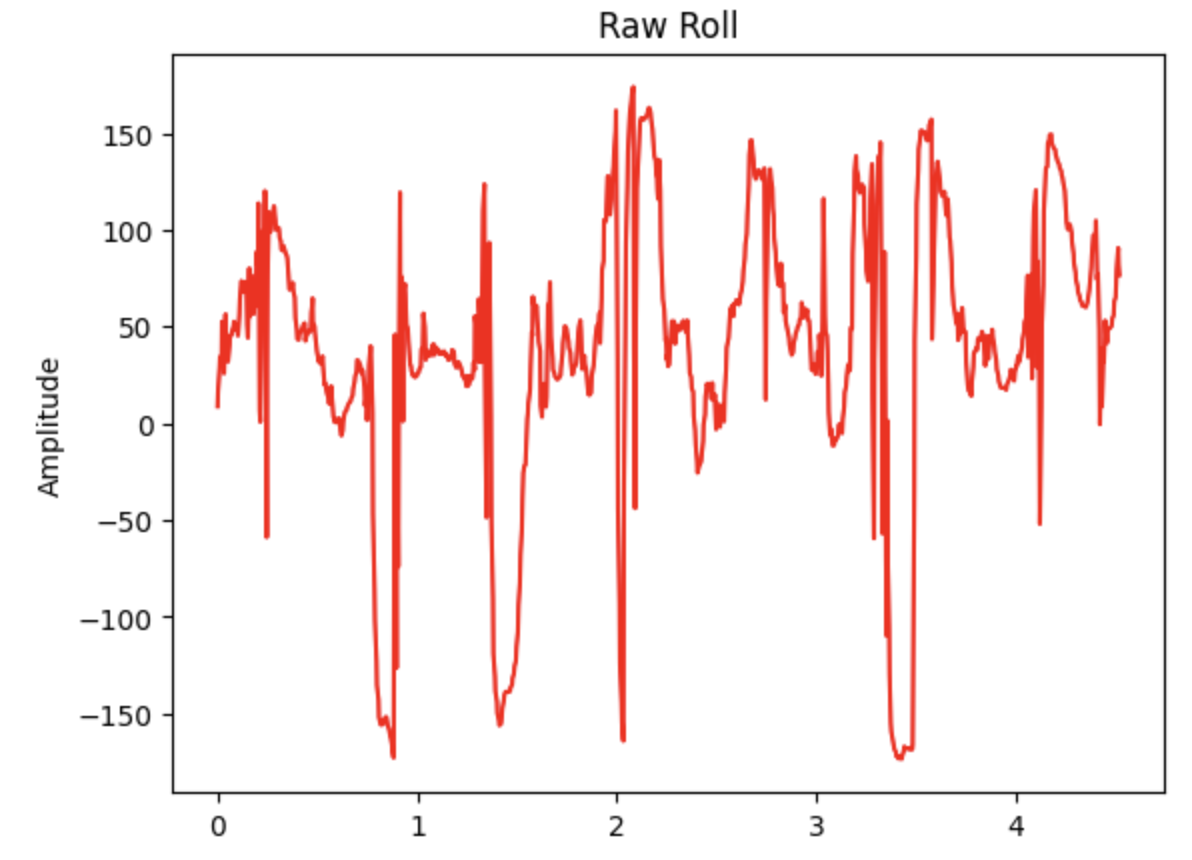
To implement this, I followed the instructions from lecture, calculating the RC value for both axes (which are the same), and using this to calculate alpha. I've included a small code snippet of this above. Running this filter on the same data shown above, you can see some spots wihere the jittery parts of the curve are smoothed out a little bit, especially on the graph for pitch.
| Roll w/o LP Filter | Roll with LP Filter |
|---|---|
 |
 |
| Pitch w/o LP Filter | Pitch with LP Filter |
 |
 |
Gyroscope
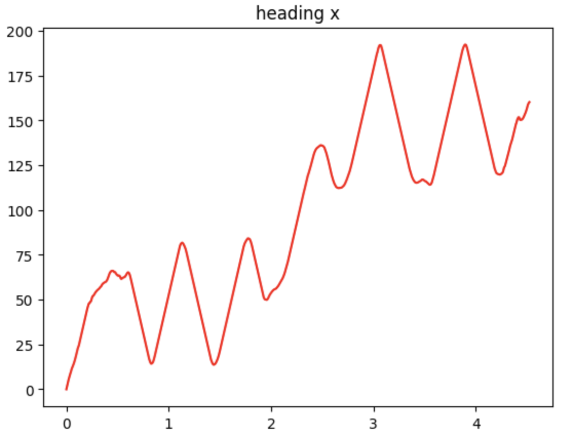
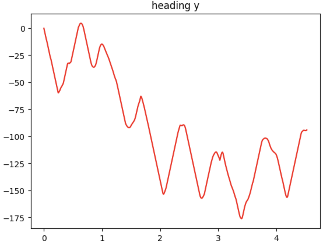
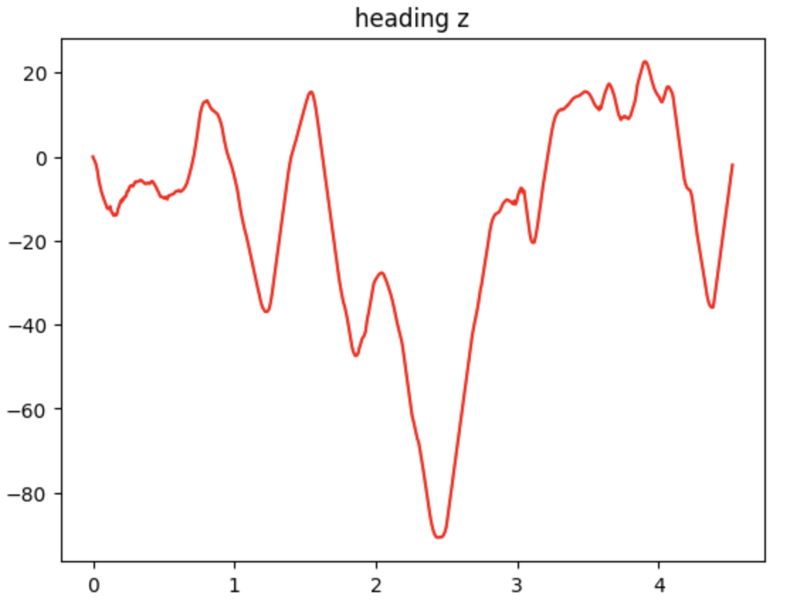
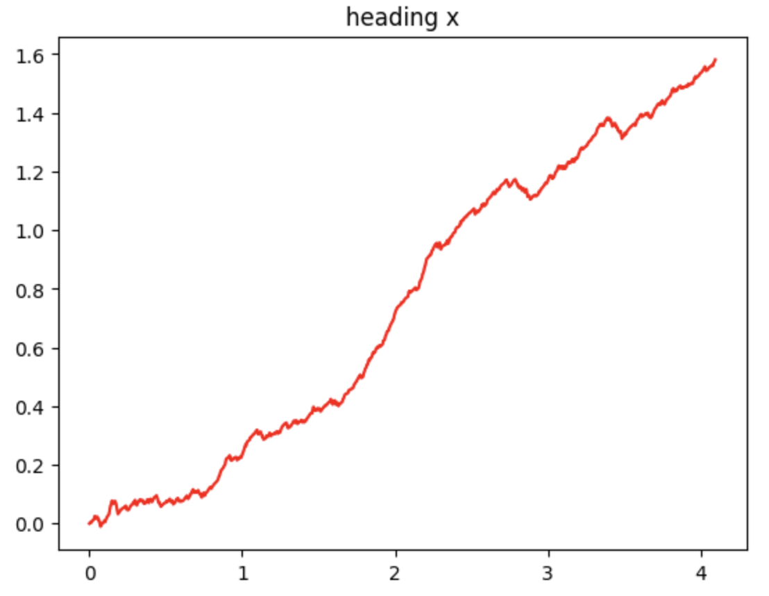
As discussed above, I implemented the integration of the gyro data to calculate heading earlier in the lab. To go in more detail, for the gyro, each data point I collected contained both the gyro data in each axes, but also a timestamp. In between each datapoint, I calculate the time delta and add its product with the gyro data to the current heading, which I initialize as 0. For the same data I've been showing above, you can see the heading calculated with gyro data below for all three axes. I additionally also included a graph the gyro-calculated X heading of a second run of the IMU where I just kept the sensor still. Here, you can see the main problem with the gyro. While the data is smooth and decently accurate, the sensor is vulnerable to drift, where the data will change over time.
| X-direction Heading | Y-direction Heading |
|---|---|
 |
 |
| Z-direction Heading | X-direction Heading w/ Drift |
 |
 |
To try to improve these results, I tested different sampling frequencies of the IMU. I found that while they all were roughly the same, higher frequencies tended to be a little bit worse with keeping a smoother signal graph (less jittering in the line), since there are more data points for noise in the data to affect the shape of the graph. However, these higher frequencies also seemed to be better at handling data of high frequencies. That is, if I moved the IMU around rapidly with my hand, measuring the IMU faster did a better job at accurately capturing all the little micro movements I induced in the sensor.
Complimentary Filter
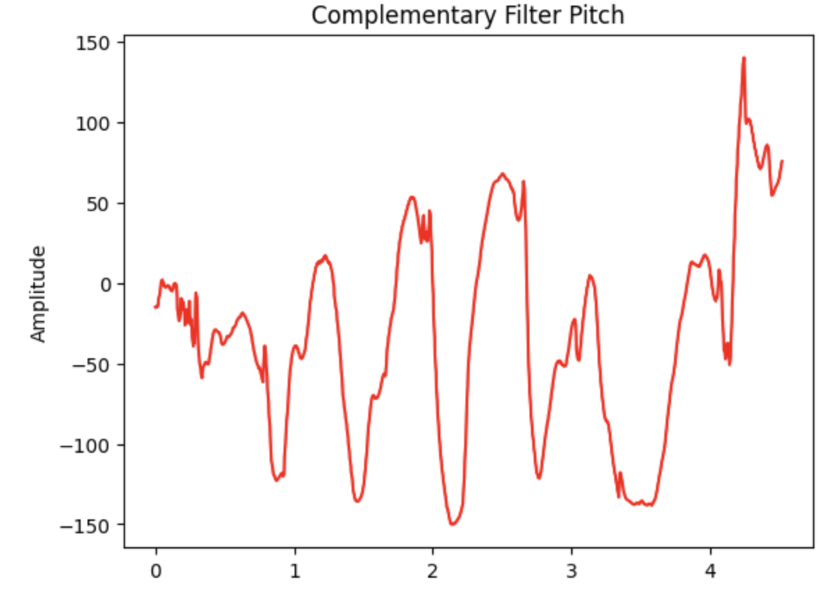
To try to get the best of both worlds, I implemented a complimentary filter to try to get the smooth signal of the gyroscope data while preventing drift using the accelerometer data. After some experimentation, I found that the drift on my gyro data was actually pretty decent, so I eventually settled on an alpha value of 0.1 which would mostly rely on the gyro data to calculate heading, with a little help from the accelerometer to prevent major drift in the signals. You can see the results below for the same data presented throughout this report, with the raw accelerometer and gyro data for comparison. Overall, I'm pretty happy with this filter, as you can still see all the major oscillations I induced on the sensor while measuring data with great detail, the resulting data curve is very smooth overall, and the drift comparison between the start and end of the data is minimal.
| Pitch from Accelerometer | Roll from Accelerometer |
|---|---|
 |
 |
| Pitch from Gyro | Roll from Gyro |
 |
 |
| Pitch from Complimentary Filter | Roll from Complimentary Filter |
 |
 |
Sample Data
Since I had read the lab beforehand, I knew speeding up the loop was coming. So, the entirety of my code was implemented to interface with bluetooth. Each section of this lab had its own unique command associated with it, which upon receiving, the robot would collect all the data necessary first before sending it all back to my laptop via bluetooth afterwards. Through experimentation, as mentioned earlier, I found that the maximum frequency that I could record data at was about 220 Hz. This seemed to be bottlenecked by my IMU sensor, as the loop could run much faster without actually waiting for it to be ready. But, considering that most IMUs on the market that are pretty affordable operate at about 10 Hz from my experience, this is more than necessary.
In terms of data storage, I had declared separate arrays for each type of data. That is, I have an array of unsigned long for timestamps, and arrys of floats for all of the roll and pitch data, as well as for the raw gyro data on all three axes. Floats were chosen for the latter since this is the native data type returned from the IMU library, and I wanted to preserve as much granularity as possible because using an int would sacrifice the decimal points, which could seriously impact accuracy. This would be most apparent in the heading calculated from gyro data, since those tiny decimal points are integrated over and over, and the error could add up fast. All in all, each datapoint contains one unsigned long for the timestamp, two floats for pitch and roll, and three floats for the gyro data on all three axes. This totals up to 4 * (2 + 3) + 4 = 24 bytes. With 384 kB of RAM, the Artemis board thus could store a theoretical maximum of 16384 datapoints. At 220 Hz, this corresponds to around 74 seconds of data, which is more than necessary to cover the 5 seconds required. In fact, the number of datapoints in the data presented throughout all of this report was carefully chosen to cover 5 seconds.
Stunt!
After working with the IMU for so long, I ended this lab by performing a stunt with my robot. Despite having a lot of issues with my controller suddenly disconnecting from the robot, I managed to record a small stunt. The robot drives into a wall, performs a small turn, and then the battery proceeds to immediately die. What a stunt! :D