Lab 3
Preview
In this lab, we connect two ToF sensors to the robot so we can measure distance from different objects. Both sensors are I2C, and we avoid address collision by shutting one sensor off to modulate the other's address. Finally, we experiment with the capabilities of these sensors, and integrate their data collection into the bluetooth functionality of the robot.
Wiring the Battery
Before I could experiment with the ToF sensors, first I soldered a JST connector onto a battery so the Artemis board can remain powered even while disconnected from my laptop via USB cable. You can see the final result below. Careful to not cut both at the same time, for each wire on the battery, I carefully cut it before stripping away about 3/4" inch of the wire casing. Using the provided JST connector, I similarly stripped away the same length of casing. Then, after twisting both bits of wire strands into one big strand, I used my preferred technique of holding the two exposed bits of wire in an "X" shape, before twisting the wire together tighltly. This approach ensures that the individual wire strands are held together and do not separate, ensuring that the whole joint acts like one single wire. The hallmark measure of whether or not the approach was executed correctly is if, without soldering, the two bits of wire stay together despite gravity when you turn it vertically. After this, I soldered the wires together and applied heatshrink to ensure the joint stays connected. This process was finally repeated for the other wire as well.

Wiring the ToF Sensors
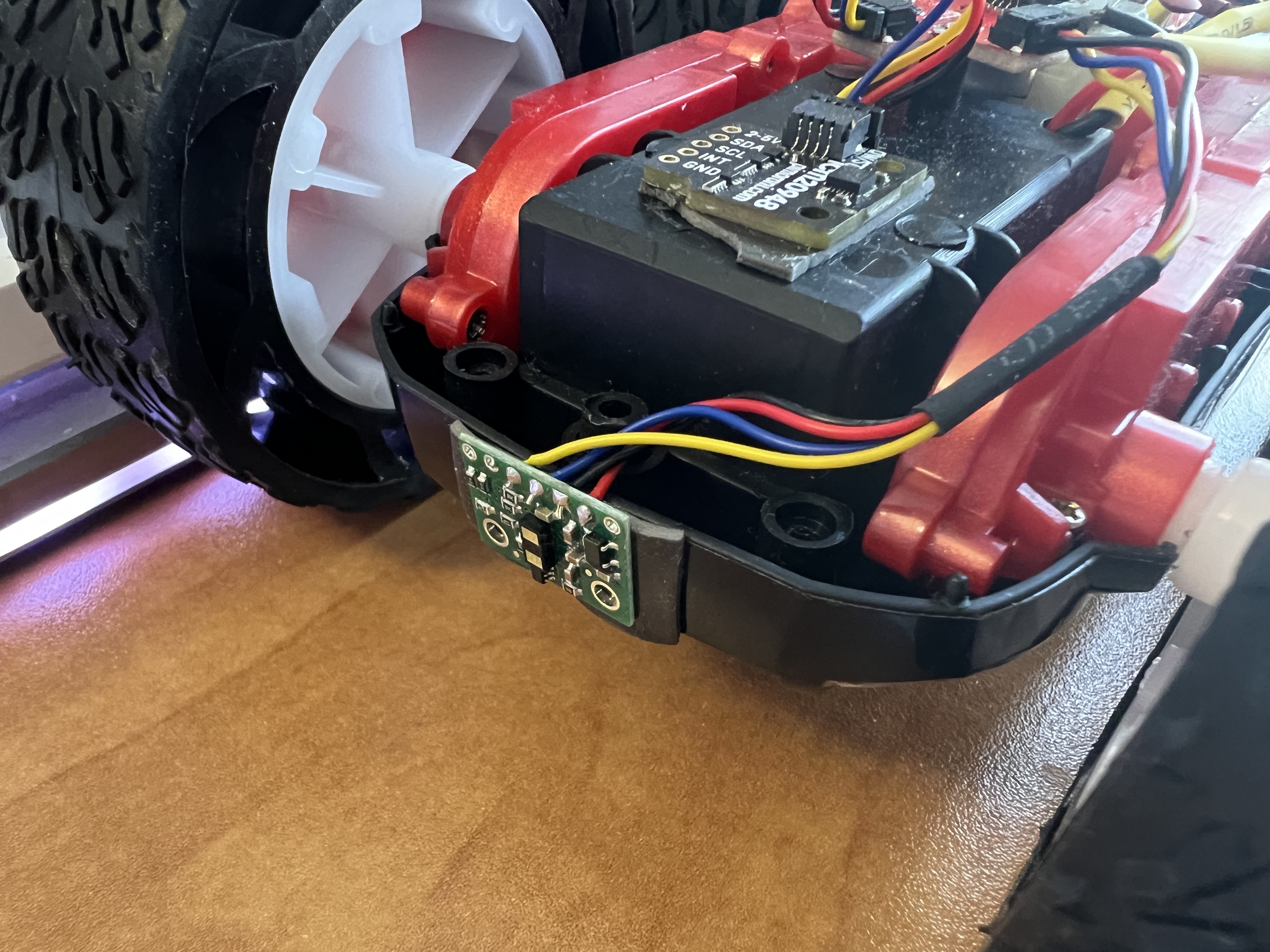
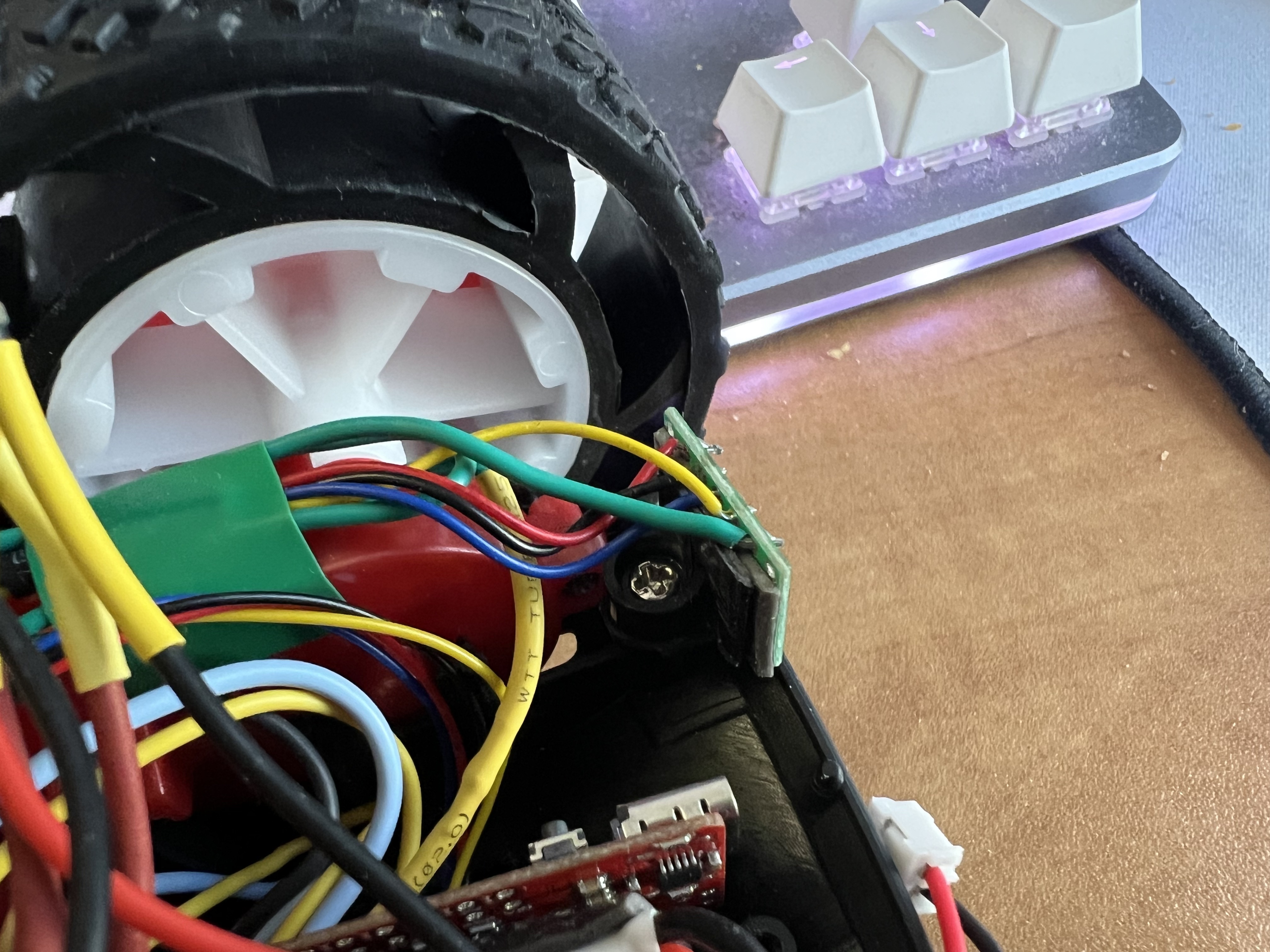
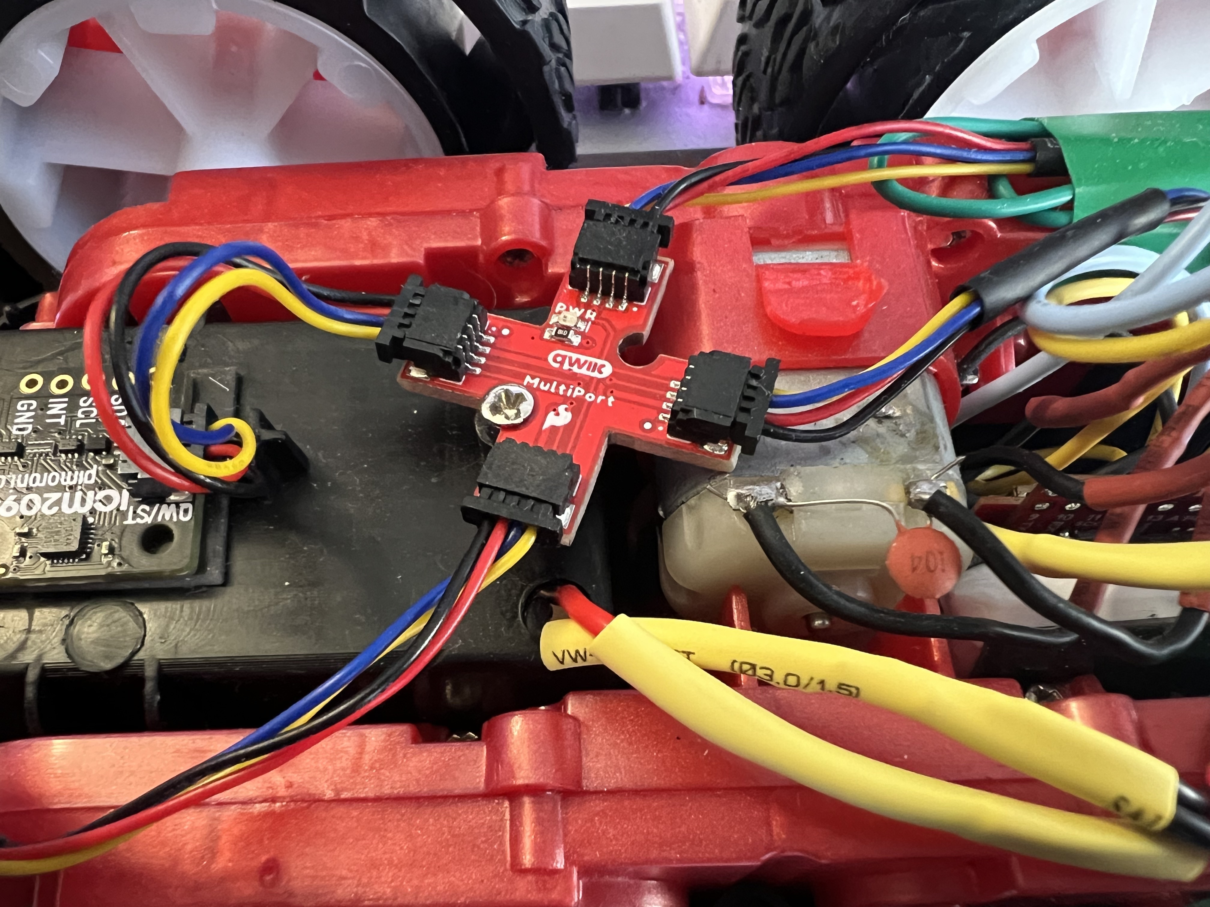
Wiring up the ToF sensors was similarly straightforward. After consulting the QWIIC breakout board and Artemis documentation, I found which position SDA and SCL were on the cables (traditionally, it is the case that VCC and GND are on the outside two pins, which also was true here). Then, I soldered wires to both of my sensors, ensuring that the color of wires I used matched those of the QWICC cables to help preserve organization. You can see this below. Note that the sensor on the rear of the robot also has an extra green wire connected to XSHUT; this is used later in the lab to enable the use of both sensors at once. Finally, you can also see the QWIIC breakout board with both ToF sensors, the IMU, and the Artemis board connected below.
| Front ToF | Back ToF | Breakout Board |
|---|---|---|
 |
 |
 |
I2C Experimentation
As instructed, I then downloaded and ran the I2C scanning example to see if my sensors were successfully connected. Since both ToF sensors have the same I2C address for now, I took turns temporarily disconnecting each sensor and running the example again. Both sensors returned an address of 0x29, which is equal to the expected address of 0101001b that the sensor's website on Polulu claims is assigned to the sensor upon startup.
Using the Sensor
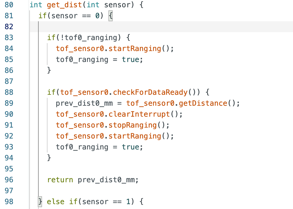
Next, I downloaded the example code to test functionality of my sensors. To do this, I added a new command in my bluetooth code which, upon receiving, the robot would measure a large number of datapoints from the ToF sensor before sending all of the data back to my laptop. However, I found a significant flaw in this approach, where the main loop would take ages to actually finish executing. After some experimentation, I found that this was due to the ToF sensor data collection call being blocking and the ToF sensor itself being pretty slow to measure new datapoints. To counteract this, I wrote a new non-blocking measuring function which would report new data if it was ready using checkForDataReady(), and if it wasn't ready, report the most recently measured datapoint, which you can see below (the near-identical code for the other sensor is omitted for brevity). While this would return without blocking, I expected it to lead to a stair-like graph, where jumps between sensor values when new data is available would be clearly visible. This turned out to be true, after running several tests where I started with my hand close to the sensor and steadily moved it further away or some similar variation. With some experimentation, I found that in comparison to the very fast speed of simply recording data that the main bluetooth loop can do, the actual sensor seemed to only report data at a maximum of about 24.2 Hz when in long distance mode, which is comparable to the expected 30 Hz listed on Polulu's website.
| Nonblocking ToF Code |
|---|
 |
Speaking of distance mode, I eventually decided to use the long distance mode due to it having the largest capable measurements. The tradeoff for this is that it has a lower theoretical maximum measuring rate of 30 Hz (which is acceptable to me since I have previously built robots with 10 Hz ToF sensors that worked fine for PID loops and etc), and that the sensor is more vulnerable to being affected by ambient light. However, some experimentation by bringing light close to the sensor found that my sensor actually was pretty resilient to such interference, even when in long distance mode.
Testing the Limits of the Sensor
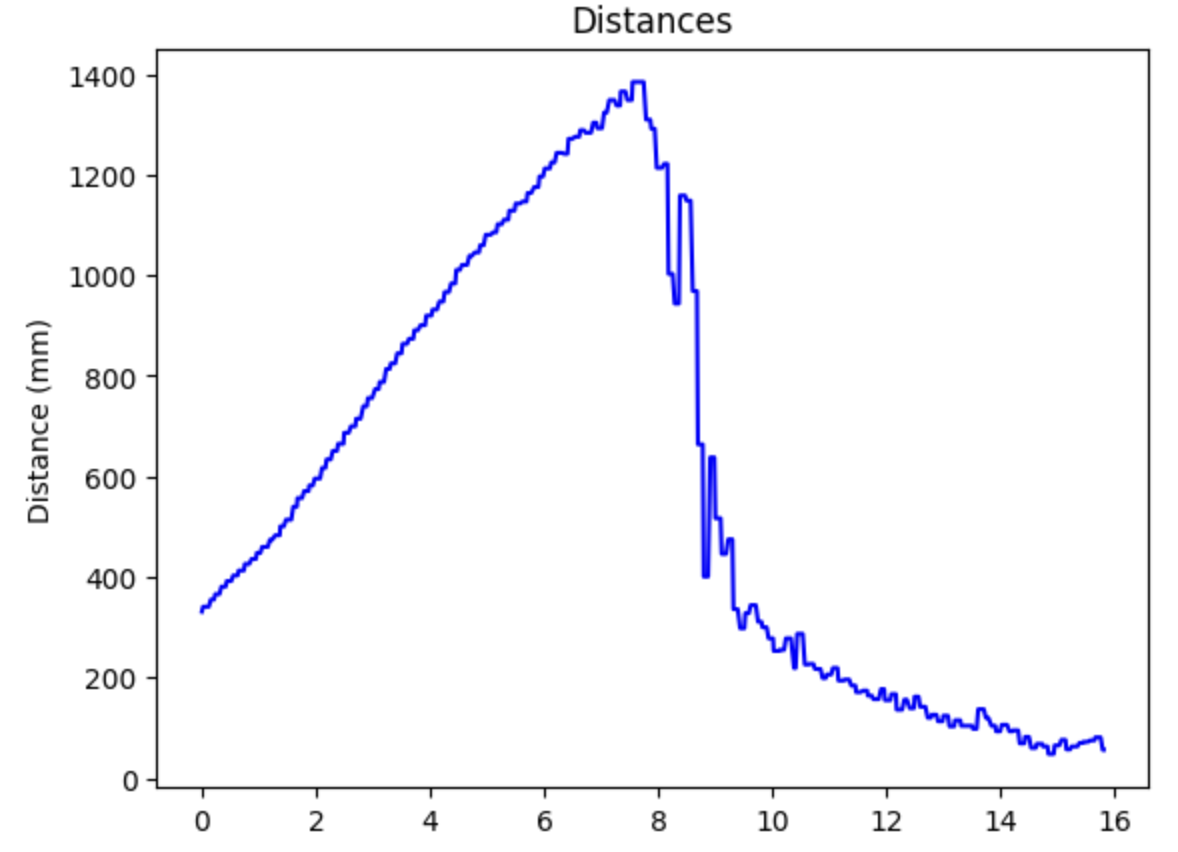
Overall, the sensor range advertised for each of the distance modes of the sensor is pretty accurate. For example, below you can see the graph of the distance of me starting close to the sensor and slowly walking out of range in short distance mode, where the data drops off once I'm no longer in range. Accuracy was also pretty good. I tested this by using a tape measure to move myself a set distance away and comparing that distance to the one measured by the sensor. The data was remarkably accurate for most distances, except when I put my hand very close to the sensor, where the distances measured by the sensor were up to around 2% larger at worst. Still, this is just a bonus, since the Polulu website does not guarentee any accuracy for distances of less than 4cm, which is what I was testing. And as mentioned earlier, the fastest measuring frequency I got out of my sensor in the long distance mode I chose was around 24.2 Hz.
Using Both ToF Sensors
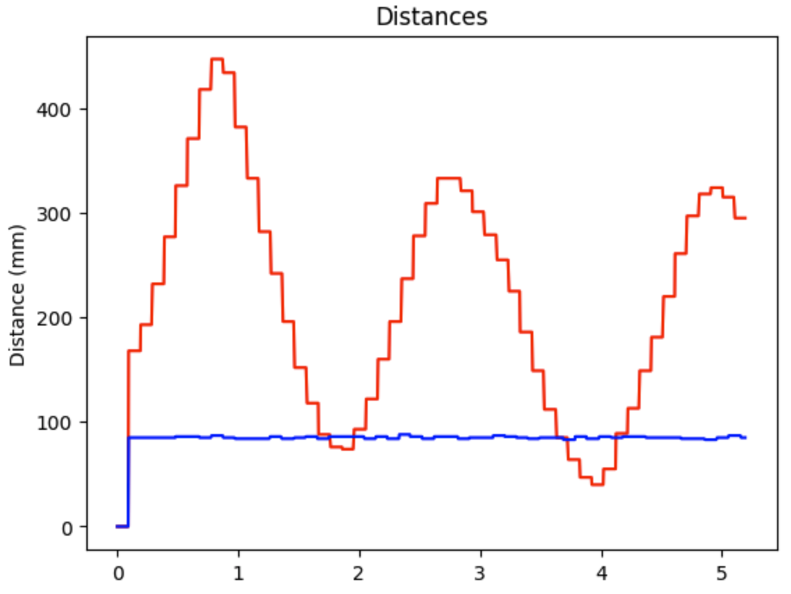
For all of the previous experimentation, I had been using one of my ToF sensors with the other unplugged, occasionally swapping which sensor I was using for rigorousness. To use both, I connected both sensors to the Artemis, and thus had to deal with the issue of address collision, since both sensors initialized to address 0x29 upon startup. To counteract this, I used my XSHUT pin I soldered onto my back-facing ToF sensor during a new setup function I wrote to initialize both sensors. Upon running this function, I write a value of LOW to the active low XSHUT pin to shut off that ToF sensor. Next, I initialize my front-facing sensor and modulate its address to 0x2A, before writing HIGH to XSHUT once again to enable me to initialize the back-facing ToF sensor with the default 0x29 address. To test this, I modified my ToF sensor command I previously wrote to measure and report data from both ToF sensors. You can see the results below of me moving one hand back and forth while holding the other still as a control.
